VIVEK DHAKAL
Classification of Hydropower Plants | Types of Hydropower Projects

Classification of Hydropower Plants | Types of Hydropower Projects


Classification of Hydropower Plants

a) Based on Purpose

1. Single Purpose Project
It is solely designed for the purpose of hydroelectricity generation.
Eg: Upper Tamakoshi Hydropower Project
       Khimti Khola Hydropower Project

2. Multipurpose Project
It is designed to fulfill more than one function or objectives. For example, the water diverted for hydroelectricity generation may also be utilized for irrigation purpose.
Eg: Bheri Babai Diversion Multipurpose Project
      Sunkoshi Marin Diversion Multipurpose Project

b) Based on Operation

1. Isolated Plant
Micro and mini hydropower plants in rural areas may be designed to serve particular village only and is not connected to the national grid is called isloated plant.

2. Grid Connected Plant
Hydropower plant with a power station feeding to a grid is called grid connected plant.

c) Based on Head

According to Dandaker and Sharma, hydropower plants can be categorized based on head as below:
Low head plants: <15m
Medium head plants: 15 - 70m
High head plants: 71 - 250m
Very high head plants: >250m

In case of Nepal, the following classification can be adopted:
Very high head plant: >350m
High head plant: 150 - 350m
Medium head plant: 60 - 150m
Low head plant: Below 60m
Very low head plant: Upto 15m

d) Based on Plant Capacity

As per Dandaker and Sharma, hydropower plants can be categorized based on capacity as below:
Micro hydel plants: <5 MW
Medium capacity plants: 5 - 100 MW
High capacity plants: 101 - 1000 MW
Super plants: >1000 MW

In case of Nepal, the following classification can be adopted:
Micro plants: upto 100 KW
Mini plants: 100 - 1000 KW
Small plants: 1 - 25 MW
Medium plants: 25 - 100 MW
Large plants: >100 MW

e) Based on Storage Capacity

1. Run of River (ROR) Project 
Those plants which do not regulate the hydrograph of source river in seasonal term, are known as ROR plants. Such plants are located in perennial river. Weir is constructed across the river to maintain the required water level u/s of weir and water is diverted into a waterway. It may have following three possible layouts:
  • ROR project with canal system
  • ROR project with pipe option
  • ROR project with tunnel option
Keeping the considerations during peak hours, ROR plants may be constructed with pondage, which can regulate daily hydrograph or weekly hydrograph and store water (full or partial) to run the plant under full capacity is called PROR plant.
General Layout of ROR type hydropower project
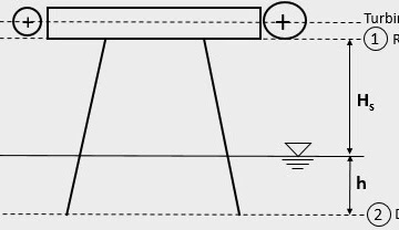
 Fig: General Layout of ROR type hydropower project

2. Storage Project
Those plants which can regulate the hydrograph of river by one or more seasons, are usually known as storage plants. Such plants are located in non-perennial rivers. A dam is constructed across the river that creates a large reservoir in front of it. It may be of following types:
  • Storage project with powerhouse at dam toe
  • Storage project with powerhouse at certain distance d/s of dam
The storage project may be of seasonal storage, annual storage, and pumped storage based on regulation of water. Pumped storage plants use excess electricity during periods of low demand to pump water from a lower reservoir to an upper reservoir. Then, during periods of high electricity demand, the stored water is released from the upper reservoir to the lower reservoir, generating electricity in the process.
What is Cavitation & its Effects in Turbine ?

What is Cavitation & its Effects in Turbine ?

What is Cavitation ?

Cavitation is a phenomenon that arises when the pressure of a liquid drops below its vapor pressure, causing the formation of vapor bubbles or cavities. Pressure drop may occur in the region of high flow velocities, for eg. at the exit of turbine runner. As the water flows through the turbine, its velocity increases. And according to Bernoulli's principle, an increase in flow velocity causes increase in velocity head and hence decrease in  pressure head since the total head always remains constant.

What Causes Cavitation in Turbine ?

When prevailing pressure falls towards vapour pressure of liquid, water starts vaporising and at the same time, normally dissolved gas gets liberated due to low ambient pressure. The water vapour and the liberated gas thus forms minute microscopic bubbles in the flowing water. When these bubbles get transported to the zone of higher pressure which is high enough to overcome the surface tension of bubbles, they get collapsed. When millions of such bubbles collapse simultaneously, a shock wave similar to water hammer but of short duration is produced which slowly causes erosion of concrete and metal surfaces.

What are Harmful Effects of Cavitation in Turbine ?

  • Erosion of concrete and metal surfaces.
  • Vibration and noise of machine parts
  • Loss of material due to pitting
  • Reducing the actual volume of liquid due to formation of bubbles

How to avoid Cavitation in Turbine ?

  • A careful streamlined design of flow passage of the runner and draft tube.
  • The sub atmospheric pressure at runner exit should be kept resonably above the vapour pressure limit.
  • By using metals more resistance to cavitation damage.
  • By periodic inspection and maintenance of turbine.
Working Principle & Functions of Draft Tube in Turbine

Working Principle & Functions of Draft Tube in Turbine

Draft tube is a pipe of gradually increasing cross-section that connects the outlet of turbine runner to the tailrace. It is used for discharging the water from exit of a reaction turbine to the tail pool and is provided only for reaction turbines eg. Francis turbine. Its cross section gradually expands and also changes its shape along its length from circular at inlet to the rectangular at the end. A draft tube plays an important role in optimizing the performance and efficiency of turbine.

Working Principle of Draft Tube


Applying Bernoulli's equation between runner exit (1-1) and draft tube outlet (2-2):
$$z_1+\frac{p_1}{\gamma}+\frac{v_1^2}{2g}=z_2+\frac{p_2}{\gamma}+\frac{v_2^2}{2g}+h_f$$
$$or, (H_s+h)+\frac{p_1}{\gamma}+\frac{v_1^2}{2g}=(\frac{p_{atm}}{\gamma}+h)+\frac{v_2^2}{2g}+h_f$$
$$or, \frac{p_1}{\gamma}=\frac{p_{atm}}{\gamma}-H_s-\frac{v_1^2-v_2^2}{2g}+h_f$$
$$or, \frac{p_1}{\gamma}=\frac{p_{atm}}{\gamma}-(H_s+\frac{v_1^2-v_2^2}{2g})+h_f \tag{1}$$
where,
$H_s$ = Static suction head
$\frac{v_1^2-v_2^2}{2g}$ = Dynamic suction head
$h_f = k\frac{v_1^2-v_2^2}{2g}$
$$or, \frac{p_1}{\gamma}=\frac{p_{atm}}{\gamma}-(H_s+\frac{v_1^2-v_2^2}{2g}-h_f )$$
$$or, \frac{p_1}{\gamma}=\frac{p_{atm}}{\gamma}-\left[H_s+(1-k)\frac{v_1^2-v_2^2}{2g}\right]\tag{2}$$
Now, draft tube efficiency can be written as:
$${\eta}_d=\frac{\text{Actual regain of pressure head}}{\text{Velocity head at entrance of draft tube}}$$
$$ =\frac{v_1^2-v_2^2}{2g}-h_f$$
$$=(1-k)\frac{v_1^2-v_2^2}{2g}$$

$$\therefore {\eta}_d=\frac{\frac{v_1^2-v_2^2}{2g}-h_f}{\frac{v_1^2}{2g}}$$
$$\therefore {\eta}_d=\frac{(1-k)\frac{v_1^2-v_2^2}{2g}}{\frac{v_1^2}{2g}}$$

From equation (2), it is clearly known that there exists a negative pressure at runner exit which is equal to $H_s+(1-k)\frac{v_1^2-v_2^2}{2g}$. From this, following two conclusions can be drawn:
  1. Due to the use of draft tube, the turbine will not lose head $H_s$ becasue of equal reduction in pressure head at runner exit.
  2. Due to use of draft tube of increasing cross-section, the pressure value at runner exit further reduced by $(1-k)\frac{v_1^2-v_2^2}{2g}$.

Purpose / Function of Draft Tube

  1. It helps to achieve the recovery of velocity head at runner outlet which otherwise would have gone to waste as an exit loss.
  2. It allows the turbine to be set at higher elevation without losing advantage of elevation difference.
  3. It serves as a passage for water from runner exit to tail pool.
Factors Affecting Selection of Foundation

Factors Affecting Selection of Foundation

Selection of particular type of building foundation is affected by various factors which are explained below:

1. Type of soil

Shallow foundation are preferred if the soil close to the surface has good bearing capacity. If the soil is not capable of supporting structural loads then deep foundation are required.

2. Load from Superstructure

If the structural loading is relatively small, shallow foundation may withstand load from superstructure. In case of high rise building with intense loading, deep foundations may become the only choice.

4. Settlement

If the foundation settlement is not within the allowable limit, then choice of foundation type may vary accordingly.

5. Property Line

Due to restriction of property line, a column may have to be placed at the edge of footing creating an eccentricity. In such case, a cantilever footing (or strap footing) should be provided.

6. Stress Overlap

If the spacing between column is very small, then the stress from independent footings might overlap and become larger than allowable limit. Thus, combined footing have to be preferred.

7. Local Building Codes & Regulations

Building codes and regulations set by local authorities dictate the minimum standards and requirements for foundation design and construction. Compliance with these regulations is essential to ensure the safety and stability of the building.

8. Environmental Factors

Environmental conditions, such as seismic activity, flooding etc need to be considered when selecting a foundation system. Regions prone to earthquakes, for example, may require specialized foundation designs to withstand the seismic forces.

9. Type of Structure in Neighborhood

High rise buildings may cause uplift of nearby building due to soil heaving. So, a pile foundation may be the solution to safely transfer load to the deep strata and not to harm the nearby structures if any.

10. Other Factors

  • Construction cost and time
  • Service life of structure
  • Safety Margin
  • Ground water table
  • Site topography
  • Depth of hard strata
Requirements of Earthquake Resistant Building Construction

Requirements of Earthquake Resistant Building Construction

An earthquake is a sudden and rapid shaking of Earth's surface caused due to the movement of tectonic plates floating on the molten rock below the surface of earth. It causes vibrations of structures and induce inertial forces on them. As a result structure may collapse resulting into loss of property and lives. Earthquakes do not kill people, vulnerable buildings do so. Hence, there is need of designing earthquake resistant buildings, especially in the earthquake prone areas. The earthquake resistance of buildings may be increased by taking some precautions and measures in site selections, building planning and building constructions which are explained below:

Improving Earthquake Resistance of Small Buildings

  • Avoid buildings in sloping grounds with different column heights.
  • Provide simple and symmetric geometry in plan.
Seismic resistant building plans
  • Avoid too many doors and windows close to each other.
  • Windows should be kept at same level.
  • In sloping roof with span greater than 6m, use trusses instead of rafters.
  • Building with four sided sloping roof is stronger than the one with two sided sloping, since gable walls collapse early.
  • Restrict the projections of chajja and balcony to maximum of 1m. For larger projections, use beams and columns.
  • Provide following RC bands:
    1. Plinth Band
    2. Lintel Band
    3. Sill Band
    4. Roof Band
    5. Gable Band
  • Offering retrofitting solutions to vulnerable structures ensures their resilience and safety is enhanced.

Improving Earthquake Resistance of High Rise Buildings

  • Provide shear walls evenly throughout the building.
  • Provide base isolation
  • Provide seismic dampers
  • Provide seismic gap in between neighbouring structures.
  • The reinforcement within structural elements should ensure adequate strength and ductility.
Concept of IEE/EIA & Its Importance in Project Development

Concept of IEE/EIA & Its Importance in Project Development

 Concept of IEE / EIA

The concept of IEE/EIA was first introduced in USA in 1970 AD under United States Environmental Law. This concept spread worldwide particularly after UN Earth Summit held in 1992 at Rio De Janeiro, Brazil. In the context of our country, government of Nepal introduced the National Environment Impact Assessment Guideline in 2050 BS. The Environment Protection Act 2053 and Environment Protection Regulation 2054 were then formulated. A new environment protection act was introduced by government of Nepal in 2076 BS. Such acts and guidelines provide a legal framework that requires developers to assess and mitigate the environmental impacts of any development project. IEE/EIA is a tool to identify and manage the effects of a development project to the environment. 

Initial Environmental Examination (IEE)

It is a preliminary environmental assessment for small projects with relatively low environmental risk. If IEE provides solutions to the identified environmental problems, then EIA is not necessary. If EIA becomes necessary, IEE serves as a valuable precursor to full EIA. The methodology involved in initial environmental examination (IEE) are as below:
  • Project description
  • Environmental screening
  • Preparation of TOR
  • Approval of TOR by concerned body
  • Conducting Environmental Assessment
  • Preparation of IEE Report
  • Submission of IEE Report
If the IEE report submitted is approved by concerned authority, the project is implimented. If it donot get approved, EIA is needed.

Environmental Impact Assessment (EIA)

It is the more extensive environmental assessment process for relatively larger project with potentially significant environmetal impacts. Its methodology includes:
  • Project description
  • Environmental screening
  • Preparation of TOR and Scoping
  • Approval of TOR and Scoping
  • Environmental Assessment
  • Preparation of draft EIA report
  • Disclosure of draft EIA report for comments and review
  • Submission of EIA report
If the EIA report submitted gets approved then the project is implimented otherwise, redesigning of project is necessary.

Principles of EIA

  1. Cost Effectiveness
  2. Transparency
  3. Certainity
  4. Participation
  5. Practicality

Difference between IEE and EIA

Difference between IEE and EIA

Importance of IEE / EIA

  • To identify the environmental impacts
  • To assess whether the impacts can be mitigated
  • To recommend the corrective and preventive mitigation measures
  • To examine the enviromental implications
  • To inform the decision makers and concerned parties about the environmental implication
  • To advise whether the development project should go ahead or not.

Specific Considerations for Hill Irrigation System in Nepal

Specific Considerations for Hill Irrigation System in Nepal

Irrigation System in Nepal

The history of irrigation development in Nepal before 1992 shows that the irrigation system was developed, operated, and maintained by farmers called Farmer Managed Irrigation System (FMIS). After that, the government of Nepal started to make efforts for the development of irrigation infrastructures in Nepal. The irrigation system in Nepal can be broadly divided into the following two parts:

  1. Irrigation System in Plains/Terai
  2. Irrigation System in Hills/ Hill Irrigation System
The irrigation system in plains (Terai regions) is usually of canal irrigation type which consists of diversion headworks, canal networks, and canal structures (cross drainage structure, canal falls/drops, cross regulators, head regulators, outlets, escapes, etc). On other hand, the hill irrigation system is a small system that taps water from small streams & river tributaries & consists of narrow, deep, and long canals with steep slopes. Sprinklers & drip irrigation systems are usually suitable for hilly regions of Nepal.

Specific considerations for design of hill irrigation system in nepal

Specific Consideration for Hill Irrigation System

1. Social Arrangements

The irrigation system adopted in hills needs to be appropriate to the culture of different ethnic groups living in hilly regions. Junior and senior water rights should also be kept in mind while designing irritation systems in hills. Village boundaries may also affect the layout of the distribution network of the irrigation system.

2. Managerial & Institutional Constraints

If farmers in the hilly regions lack managerial & institutional capabilities & cannot be trained effectively within the available time period, then the distribution system should be simplified and control structures should be minimized. The regulating structures should be made easy to operate by local farmers.

3. Agricultural Considerations

The irrigation system proposed should also be compatible with the type of soil present in the hilly region. Also, the irrigation system should be suitable for the type of crops to be cultivated in hilly areas.

4. Financial Considerations

The choice of technology, methods of construction, type of materials to be used, etc may be restricted due to financial limitations.

5. Design Considerations

  • Farmers' Participation in Engineering Design
Because of intimate familiarity with the local conditions, farmers may help to better estimate the design flood discharge, flood level in the river, boulders & sediments carried by the river, etc. By providing these facts, farmers can help designers to avoid costly mistakes.
  • Field-Based Design
Decisions regarding where to place the structure, what type of structure to be built, etc should be taken in the field since the structures in hills are affected by various topographical factors of the hilly region.
  • Design Standards
Design standards while designing structures in hill irrigation systems should be considered wisely. Adoption of higher design standards (structural & operational) may be unrealistic as the structures built in hill irrigation systems are subject to frequent flooding, landslides, rock falls, soil erosion, etc.
  • Canal Design
Large canal sections should not be built on unstable hill slopes. Canal beds may be steep to increase the flow velocity & thus to reduce the seepage loss via canal beds. Canal linings may be done with locally available materials in hilly regions.

Importance & Requirements of Highway Drainage

Importance & Requirements of Highway Drainage

Water has detrimental effects on the good performance of road & should be drained off as soon as possible. The process of quick removal of water out of surface & sub-surface region of the road is called Highway Drainage. The surface & sub-surface water of the road should quickly pass into the longitudinal drains if a proper highway drainage system is present. The surface water passes into longitudinal drains via gravity flow due to the cross-slope provided on the road surface. The subsurface water first goes into the perforated cross drains & then into the longitudinal drains, both being under the road surface in the areas of heavy rainfall. The surface drainage system prevents the surface water from percolating down to the sub-surface layers. The sub-surface drainage system takes the sub-surface water out of the subsurface layers.

What is the Importance of Highway Drainage?

The provision of a proper drainage system provides the following important functions:
  1. It arrests the moisture variation in the subsurface layers thus preventing the reduction in bearing capacity of subgrade soil.
  2. It prevents the erosion of side slopes.
  3. It prevents the failure of formation slope caused by the poor drainage system.
  4. It prevents the stripping of bitumen from aggregates in flexible pavements.
  5. It prevents the mud pumping in rigid pavements.
  6. It prevents the skidding of vehicles caused by a reduction in friction coefficient.
  7. It prevents the frost action caused by the accumulation of water.

What are the Requirements of a Good Highway Drainage System?

A good highway drainage system should fulfill the following requirements:
  1. The surface water on the carriageway and shoulder should be drained off effectively as soon as possible.
  2. The surface water from the adjoining land should be prevented from entering into the roadway.
  3. The groundwater table should be maintained well below the bottom surface of the subgrade soil.
  4. The capillary rise & seepage water should be controlled effectively.
  5. The longitudinal drains & cross drains should have sufficient capacity to carry the collected water.
  6. The longitudinal drains & cross drains should have sufficient bed slope for gravity flow.
  7. The flow of water across the road surface & in the drains should not cause erosion.
  8. Complex & costly cross drainage structures should be avoided as much as possible.
Road Classification in Nepal | Nepal Road Standard 2070

Road Classification in Nepal | Nepal Road Standard 2070

Roads in Nepal are classified according to different guidelines & standards developed by the government of Nepal. The major guidelines are Nepal Road Standard 2070 (NRS 2070), Nepal Rural Road Standard 2071 (NRRS 2071), Nepal Urban Road Standard 2076 (NURS 2076), etc.

Nepal Road Standard 2070

According to Nepal Road Standard 2070, the roads in Nepal can be classified as follows:
  • Administrative Classification
    • National Highways
    • Feeder Roads
    • District Roads
    • Urban Roads
  • Technical/Functional Classification
    • Class I
    • Class II
    • Class III
    • Class IV

Administrative Classification

Administrative classification of roads is intended to assign national importance & level of government responsible for the overall management and financing methods.
1. National Highways
These are the major roads running east to west & north to south of the country.
2. Feeder Roads
These are the roads connecting the district headquarters, major economic centers & tourism centers to national highways or other feeder roads.
3. District Roads
These are the roads within a district, serving areas of production & markets, and connecting with each other & with the main highways.
4. Urban Roads
These are the road within an urban municipality.

In Nepal, the overall management of national highways & feeder roads comes under the responsibility of the Department of Road (DOR). And these roads are collectively called Strategic Road Network (SRN). The district roads & urban roads fall under the responsibility of the Department of Local Infrastructure Development & Agricultural Roads (DOLIDAR). And these roads are collectively called Local Road Network (LRN).

Technical / Functional Classification

Road Classification in Nepal

Nepal Rural Road Standard 2071

According to Nepal Rural Road Standard 2055, 2nd revision 2071, the rural roads in Nepal are classified as below:
  • District Road Core Network (DRCN)
  • Village Road
1. District Road Core Network (DRCN)
It is an important road joining a VDC HQ's office or nearest economic center to the district headquarters, via either a neighboring district headquarters or the Strategic Road Network.
2. Village Road
Smaller roads not falling under District Road Core Network category are Village Roads, including other Agricultural Road.

Nepal Urban Road Standard 2076

According to Nepal Urban Road Standard 2076, the urban roads are classified as follows:
  • Arterial Roads (Path)
  • Sub-arterials Roads (Sadak)
  • Collector Roads (Marg)
  • Local Roads (Upa-Marg)
1. Arterial Roads (Path)
These are the roads generally meant for through traffic usually on a continuous route.
2. Sub-arterial Roads (Sadak)
These are the roads of the somewhat lower levels of travel mobility than the arterial roads.
3. Collector Roads (Marg)
A collector road is one intended for collecting & distributing traffic to and from local roads & also providing the access to arterial/sub-arterial roads.
4. Local Roads (Upa-Marg)
A local road is one primarily intended for access to the residence, business, and other abutting property.
What are the Special Considerations for Hill Road Alignment?

What are the Special Considerations for Hill Road Alignment?

What is Hill Road?

According to Nepal Rural Road Standards (2055), 2nd Revision 2071, the terrain is classified as Terai & Hills based on the topography of the country. The Terai covers the plain & rolling terrain having a cross slope of 0 to 25%. Hill covers the mountainous & steep terrain having a cross slope of 25 to 60% and more. The road passing through the hilly terrain with a cross slope of 25% or more is generally termed as Hill Road. A hill road usually consists of either a river route or a ridge route.

Factors affecting alignments of hill roads

What are the Factors Affecting the Alignment of Hill Roads?

There are various factors affecting road alignment. Moreover, there are some special considerations to be followed while selecting a hill road alignment. The major factors to be considered while deciding the alignment of hill roads are as follows:

1. Geological Stability

The road alignment should pass through a stable hill slope. The area should not be prone to erosion, landslides, rockfall, etc.

2. Availability of Construction Materials

Availability of construction materials near the construction site will reduce the transportation cost of materials thus making the project economical.

3. Cross Drainage Structures

Due to numerous watercourses present in the hilly regions, there may be the necessity of intense cross drainage works. The alignment should be so selected in such a way that the number of cross-drainage structures required becomes minimum.

4. Geological Structures

Excessive cutting of hard rock will be expensive. So, such areas should be avoided as much as possible from the road alignment.

5. Geometric Design

The alignment should be chosen to minimize the ineffective rise & fall, steep gradients, number of hairpin bends, etc. Also, the geometric design parameters should comply with the design guidelines & standards for hilly regions.

6. Altitude of the Road

  • Rainfall (or Snowfall) ∝ Altitude
  • Atmospheric Pressure ∝ $\frac{1}{Altitude}$
  • As the altitude decreases, the number of cross drainage works required increases.
Basics of Tunnel Engineering | Methods of Tunnelling

Basics of Tunnel Engineering | Methods of Tunnelling

Methods of tunneling in Civil Engineering

Tunnels are underground passages used for transportation purposes. Tunnels are the underground routes driven without disturbing the overlying soil to bypass the obstacles safely. Tunnels can be used to carry passengers & freights, water, sewers, gases, etc. Tunnels are constructed in various shapes & sizes. The shape of the tunnel cross-section is governed by the nature & type of ground to be penetrated, existing overburden stress on the rock, etc while the size of the tunnel depends on the usage to which it is subjected. The economy of tunnel construction depends on the relative cost of open cuts vs. tunnelling. The tunnel becomes more economical than an open cut beyond a certain depth.

Advantages of Tunnelling

  • It reduces the route distance & travel time
  • It provides easy gradients in hilly terrain
  • Surface activities are not disturbed
  • It remains free from the weather actions like rainfall, snow, etc.
  • The tunnel becomes more economical than an open cut beyond a certain depth.

Disadvantages of Tunnelling

  • The initial cost of construction may become higher
  • Construction of tunnel requires skilled manpower & sophisticated equipment
  • Strick supervision is necessary during construction
  • Higher safety precautions are necessary during construction
  • Construction of tunnel requires more time than open cuts
  • A tunnel may collapse during an earthquake

Terminologies related to Tunnel Engineering

  • Tunnel Portal: It is the entrance or exit of tunnel where tunnel intersects with the open area. It may be an inlet portal or outlet portal.
  • Crown: It is the topmost point of the tunnel cross-section.
  • Invert: It is the lowest point of the tunnel cross-section.
  • Faces of Operation or Attack: It is the surface from which a boring operation is carried out.
  • Adit Tunnel: It is a horizontal or near-horizontal passage that provides access for extra faces of operation/attack in addition to the inlet face and outlet face. It may also be used for the purpose of the auxiliary entrance, ventilation, drainage, etc.
  • Inclined/Vertical Shaft: It is an inclined or vertical passageway that connects the surface to the underground tunnel or network of tunnels.
  • Pilot Tunnel: It is a small tunnel driven, parallel & close to the proposed main tunnel, to explore geological conditions & assist in final excavation. During construction of vertical shaft, a pilot tunnel is excavated at first.
  • Tunnel Linings: These are the supports erected during & after tunnel construction to ensure a safe working environment inside the tunnels. Rock bolts, steel ribs, wire mesh, shotcrete, etc are used as tunnel lining materials.
  • Mucking: Mucking means the removal of blasted debris from the tunnel interior to a good distance outside the tunnel entrance.
  • Overbreak: It is the over excavation beyond the intended boundaries, resulting in a larger opening or void than originally intended.
  • Niche: It is the relatively small recesses or compartments excavated inside a tunnel for specific purpose such as equipment housing, utility installation, for vehicles to make turns or change direction, etc.
  • Cavern: Caverns are intentionally excavated larger underground chambers for construction of specific underground structure such as an underground powerhouse. In tunnelling, niches and caverns are both types of excavated spaces within the tunnel structure, but they differ in terms of size, purpose, and construction methodology.
  • Grouting: Grouting is a process where a fluid material, often cement-based, is injected into the ground to improve soil or rock properties.
  • Overburden: Overburden refers to the soil, rock, or other material that lies above the tunnel roof or crown.

A. Based on Purpose

  1. Traffic Tunnel
    • Highway Tunnel
    • Railway Tunnel
    • Pedestrian Tunnel
  2. Conveyance Tunnel
    • Power Tunnel
    • Water Supply Tunnel
    • Sewer Tunnel

B. Based on Shape/Cross-Section

  1. Circular Tunnel
  2. D Shaped Tunnel
  3. Horse Shoe Tunnel
  4. Square or Rectangular Tunnel
  5. Elliptical Tunnel

Methods of Tunnelling

During tunnel construction, tunnels are lined with suitable materials parallelly with the boring operations. Tunnels are usually lined with timber, steel, cast iron, masonry, or concrete with suitable outlets to let out the enclosed subsoil water behind the linings. Other items of work include the provision of ventilation, drainage, lighting, etc. Tunnelling may have to be done in the hard rock or soft soil based on which the method of tunnelling differs. Hard rock is considered as a fully self-supporting soil that does not require much support except where a loose rock is occasionally met. On the other hand, soft soils like running grounds (eg: water-bearing sands) require instant supports all around. So, different methods of tunnelling based on the nature of the soil to be penetrated are listed below:

A. Tunnelling in Soft Ground

  1. Fore Poling Method
  2. Needle Beam Method
  3. Shield Method
  4. Compressed Air Method
  5. Liner Plate Method
  6. Army Method
  7. American Method

B. Tunnelling in Hard Rock

  1. Full Face Method
  2. Top Heading Benching
  3. Bottom Heading & Stopping
  4. Drift Method
  5. Pilot Tunnel Method
For the detailed description of each method of tunnelling listed above, the readers are kindly requested to go through ref 1.

References
  1. Srinivasan, R.(1958). Harbour, dock and tunnel engineering. India: Charotall Book Stall
What are the Factors Controlling Highway Alignment?

What are the Factors Controlling Highway Alignment?

What is Highway Alignment?

The process of establishing the centerline of a road is called highway alignment or Road alignment. It the direction through which the highway will pass. Highway alignment can be divided into two parts as Horizontal Alignment & Vertical Alignment. The horizontal alignment is seen in the plan of the road & it consists of the straight path, horizontal curves, etc. The vertical alignment is observed in the longitudinal profile of the road & it contains verticle curves, gradients, etc.

What are the Requirements of Highway Alignment?

An ideal highway alignment may fulfill the following criteria:
  • Short: The route between any two points should be the shortest route.
  • Safety: The alignment should satisfy the safety requirements.
  • Comfort: The alignment should have easy curves & gradients.
  • Economy: The cost of construction should be economic.

What are the Factors Controlling Highway Alignment?

There are various factors to be considered while selecting a road alignment. Additionally, there are some special considerations to be followed while selecting alignments in hill roads. In general, the following factors are to be considered while choosing a highway alignment.

1. Government Plannings

Since a road project involves heavy investments, it should comply with government requirements & planning.

2. Obligatory Points

Obligatory points are the governing points that control the highway alignment. These can be classified into two types viz. the points thorough which alignment should always pass (or positive obligatory points) & the points through which the alignment should never pass (or negative obligatory points). Ex: Highway alignment should always pass through the bridge site. In the case of mountains in the alignment, there may be options either to go round the hill or to construct a tunnel. Moreover, the highway alignment should never pass through the National Parks, Conservation Areas, Protected Areas, dense forest, costly agricultural lands, etc. In the case of an intermediate town, the highway alignment may get deviated slightly in order to connect the town.

3. Traffic Flow Pattern

The traffic flow pattern can be known from the origin & destination study (O&D Study). The lines are drawn in the data obtained from the origin & destination study & then, proper alignment is fixed.

4. Geometric Design

The road alignment is also affected by the geometric design. The horizontal curves, vertical curves, gradients, sight distance, etc should meet the requirements of geometric design standards.

5. Monotony

Due to very long straight paths in flat terrain, the driver may become monotonous & this may lead to accidents. Thus, small horizontal curves should be provided in suitable intervals to avoid monotony.

6. Economy

The alignment should be selected in such a way that the construction cost, maintenance cost & operation cost of the road is minimum. Excessive cuttings & fillings, the necessity of complex structures, etc should be avoided.

7. Railway Crossings

A highway alignment should cross the railway alignment preferably at a right angle.
Objectives & Methods of River Training Works

Objectives & Methods of River Training Works

Definition of River Training

The process of controlling the flow in river & river bed configuration is called river training works. These are the structural measures adopted in rivers to avoid outflanking & shifting its thalweg due to geomorphological changes in the river. So, the river training works stabilize the river channel along a certain alignment.
Methods of Soil Compaction | Types of Soil Compaction

Methods of Soil Compaction | Types of Soil Compaction

Methods of soil compaction
Compaction of soil is necessary for various types of foundations used in civil engineering constructions. It improves the engineering properties of soil. Compaction is the process of reducing air voids in soil by means of mechanical compressions. During compaction, the air is expelled from the voids in the soil. It increases the dry density of soil, improves shear strength & hence stability and bearing capacity. The various methods of soil compaction are as follows:
  • Tamper / Rammer
    • Hand Operated Tamper
    • Mechanical Tamper
  • Roller
    • Smooth Wheeled Roller
    • Pneumatic Tyred Roller
    • Sheep Foot Roller
  • Vibrator
Types of Foundation Used in Civil Engineering Constructions

Types of Foundation Used in Civil Engineering Constructions

Every civil engineering structure, whether it is a building, a bridge, or a dam, is founded on or below the surface of the earth. Foundations are required to transmit the load of the structure to the foundation soil safely & efficiently. Different types of foundations used in civil engineering constructions can be classified as follows:
Types of foundations used in Civil Engineering constructions

Shallow Foundation

According to Terzaghi, a shallow foundation is one whose width is greater than its depth. i.e. Df/B<1. Such a foundation transmits the load to the upper strata of the earth & is generally provided to the lightweight structures. It is preferred when foundation soil has sufficient bearing capacity at shallow depth. When the sum of areas covered by each isolated footings is more than 50% of the total area of the foundation, mat foundation is adopted.

Strip or Wall Footing

Strip or Wall Footing

Isolated or Spread Footing

Isolated or Spread footing used in Civil Engineering constructions

Combined Footing

Combined footing used in Civil Engineering constructions

Strap or Cantilever Footing

Strap footing or cantilever footing

Mat or Raft Foundation

Types of Mat or Raft Foundation

Deep Foundation

A deep foundation is one whose width is less than its depth i.e. Df/B>1. Such a foundation transmits the load to the strata at a considerable depth below the surface of the earth & is provided to the heavyweight structure. It is preferred when the soil at the surface of the earth does not possess a considerable bearing capacity. The most common types of deep foundations are piles, piers & caissons. Well foundations are the special case of open caissons.
Types of deep foundation used in civil engineering constructions
What are the Criteria for Selection of Ideal Bridge Site?

What are the Criteria for Selection of Ideal Bridge Site?

Criteria for selection of ideal bridge site
It is necessary to select an ideal bridge site at which the bridge can be made economically. As construction of a bridge requires a heavy investment, the bridge site should be selected wisely. A poor bridge site may increase the project's cost, making it susceptible to damage, in the long run, thus decreasing the life span of bridges. Thus, the following are the factors that require attention while selecting a bridge site.
Principles & Techniques of Bioengineering for Civil Engineers

Principles & Techniques of Bioengineering for Civil Engineers

In a broader sense, Bioengineering is the use of life science & engineering to solve human life problems. Here, in this article, we are using the term bioengineering in the context of civil engineering & it basically refers to soil bioengineering. So, Bioengineering can be defined as the use of vegetative measures & small civil engineering structures in order to reduce the shallow seated instability. The living plants or non-living plant materials are used alone or in conjunction with small civil engineering structures for slope stabilization & erosion control. It utilizes locally available resources & is a cost-effective method.

Principles of Bioengineering

Initially, stability is obtained from the small civil engineering structures. The strength of those structures decreases gradually. After the handover point, stability is derived from the vegetative measures. This can be depicted from the graph shown below:
Principles of Soil Bioengineering

Functions of Bioengineering

Engineering functions performed by vegetation on a slope are as follows:
  • Catch
  • Armor
  • Reinforce
  • Anchor
  • Support
  • Drain

Advantages of Bioengineering

  • Immediate slope stabilization & erosion control
  • Utilization of locally available resources (local tools, local manpower, local materials)
  • It is a cost-effective method
  • No need for frequent maintenance
  • It also provides an opportunity for wildlife habitat
  • It also improves the aesthetic beauty of the site

Commonly Used Techniques of Bioengineering

  • Fascine: Bundle of live branches laid in shallow trenches
  • Palisade: Woody cuttings planted across the slope.
  • Wattling: Fence made out of vegetative materials.
  • Bamboo Planting: Planting of bamboo for soil conservation
  • Grass Planting: Planting of grass across the slope
  • Brush Layering: Layers of woody cuttings planted in line following the contour
  • RipRap: Stone pitching with vegetation interplanted between them
  • Retaining Wall: Wall built to resist the pressure of earth filling or backing
    • Toe Wall
    • Breast Wall or Revetment Wall
  • Check Dam: Dams constructed across the gullies to retard the flow
  • Gabion Wall: Walls made up of gabion wire filled with stones
  • Stone Masonry: Masonry construction using stones & mortar 
  • Jute Netting: Protecting the slope with standard jute mesh
  • Rock Netting: Wire mesh of reliable material used to control the rockfall
  • Rock Bolting: Reinforcement of rock slope by inserting steel bars
  • French Drain: Subsurface drainage channel filled with aggregates
Degree of Static & Kinematic Indeterminacy of Structures

Degree of Static & Kinematic Indeterminacy of Structures

A structural system that can be analyzed by using the equation of static equilibrium only is called statically determinate structure i.e. reaction components and internal stresses can be calculated using static equilibrium equations only. Eg: Simply supported beam. If it cannot be analyzed by the equation of static equilibrium alone, then it is called a statically indeterminate structure. Eg: Fixed beam. A structural system is said to be kinematically indeterminate if the displacement components of its joints cannot be determined by the compatibility equation alone. Eg: Simply supported beam. If those unknown quantities can be found by using compatibility equations alone then the structure is called kinematically determinate structure. Eg: Fixed beam. But before calculating the degree of indeterminacy of a structure, it is good to know about its stability. If a structure is unstable, then it doesn't matter whether it is statically determinate or indeterminate. In all cases, such types of structures should be avoided in practice.