VIVEK DHAKAL
Diversion Headworks in ROR Type Hydropower Plant

Diversion Headworks in ROR Type Hydropower Plant

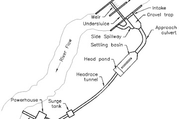
Fig: Schematic Diagram of Headworks Components in ROR Type Hydropower Plant

Hydropower plants may be of different types. Based on the type of hydropower plants, the general arrangement and components in headworks may vary. For example, a run of river hydropower plant generally consists of a weir and undersluice structures separated by a divide wall where as in a storage type hydropower plant, it consists of a dam and reservoir system with an spillway sitting on the dam crest. Here, in this article, the major components of diversion headworks in typical ROR type hydropower plant are described. The principal function of each components of headworks are as follows:

Components & Function of Diversion Headwork in Typical ROR Type Hydropower Plant

1. Weir

  • To raise the water level upstream of the weir that builds the sufficient driving head to divert water into the water way.
  • To allow safe passage of flood through the weir crest.

2. Underlsuice / Scouring Sluice

  • To create a still pocket of water in front of the intake so that sediment free water can be withdrawn thorough it.
  • To flush sediments deposited in front of the intake by opening undersluice gates.
  • To allow a portion of flood discharge to pass safely through it.

3. Divide Wall

  • To separate the weir and under sluice portions from each other
  • Helps to keep the comparatively less turbulent pockets of water by preventing cross currents near the intake area

4. Intake

  • To regulate supply of water into the waterway
  • To control entry of sediment and trashes into the waterway
  • To prevent flood entering into the waterway

5. Fish Ladder

  • To allow migratory fishes to travel between upstream and downstream of weir

6. River Training works such as Flood Walls, Boulder Riprap, etc.

  • To prevent flooding of surroundings by safe passage of flood discharge
  • To prevent river eroding the river banks
  • To prevent river from changing its course

7. Gravel Trap

  • To settle coarser sediments entering into the intake
  • To avoid small trashes that has passed through intake
  • To escape excess water through side spillway if any.

8. Approach Canal / Approach Culvert

  • To convey water from intake and gravel trap to settling basin
  • To maintain straight approach and controlled velocity before settling basin.

9. Settling Basin

  • To settle fine sediments and silts and to flush them out
  • To escape excess water through side spillway if any.

10. Head Pond / Forebay

  • To maintain submergence for pressure conduit
  • To escape excess water through side spillway if any.
  • It also serve the function of head regulation.
Forebay & Its Functions in Hydropower Plant

Forebay & Its Functions in Hydropower Plant

What is Forebay in Hydroelectric Power Plant ?

It is a structure located at the beginning of penstock pressure shaft that satisfy the function of head regulation and elimination of water hammer effect. It is a large water body that fulfills similar functions as the surge tank. A forebay is sometimes also referred as head pond. A forebay may consists of trash rack at the beginning of penstock pipe. The functions of a forebay can be pointed as below:
  • It allows transition of watercourse from open channel flow to pressurize flow maintaining the necessary submergence.
  • It protects the penstock pipe form water hammer effect caused due to sudden acceptance and rejection of load in turbines.
  • Temporary storage of water when load on turbine is suddenly decreased.
  • Temporary supply of water when load on turbine is suddenly increase.
  • It serves the function of head regulation.
  • Spilling of excess water through side spillway if any.

What is Difference Between a Surge Tank & Forebay ?

A surge tank or a fore bay is constructed in a hydroelectric power plant with the same purpose of eliminating the effect of water hammer. But a surge tank is constructed when there is a pressurized flow in headrace that feeds to surge tank where as if the headrace flow is of open channel type, then construction of forebay is necessary.
Functions & Types of Penstock in Hydropower Plant

Functions & Types of Penstock in Hydropower Plant

Penstock pipe in hydropower plant

What is Penstock in a Hydropower Project?

A penstock is a steeply sloping pipe that carries water at high pressure from surge tank or a forebay to the turbine. It is designed to operate under very high head of water with least possible head loss. A penstock pipe experiences heavy stress and vibration due to the effect of water hammer during sudden closure of valve that control flow to the turbine. Anchor blocks and support piers are provided along the span of the penstock pipe in order to held it firmly in its position. Expansion joints are provided in case of long penstock pipes so as to avoid the forces due to thermal expansion and contraction. These joints are usually placed immediately downstream of an anchor block. A penstock pipe may have vertical and horizontal bends as per the project needs. It may have bifurcation or trifurcation before it enters into the powerhouse so as to feed the different turbine units. The major and minor head loss in penstock pipe can be determined as explained in pipe flow literature. A penstock pipe may be of following types:
  • Exposed Penstock
  • Embedded Penstock
  • Buried Penstock
A penstock pipe in hydropower plant serves following different functions:
  • To convey water from surge tank to the turbines with minimum loss of head
  • To withstand the effect of water hammer during sudden closure of valve

What is Economical Diameter of Penstock?

The economic diameter of penstock is a diameter which minimizes the sum of annual cost of penstock pipe and annual value of power loss due to loss of head in the penstock pipe. The diameter of penstock pipe can be optimized either by analytical method or by graphical method so as to obtain the economical diameter of pipe.
Water Hammer & Surge Tank in Hydropower Plant

Water Hammer & Surge Tank in Hydropower Plant

Working principle of surge tank

Concept of Water Hammer

In a long pipe, when velocity of liquid is abruptly decreased as a response to the operation of flow control device (eg: valve closure), the momentum of liquid gets destroyed. As a result, the kinetic energy of liquid is converted into internal pressure energy due to which a wave of high pressure is set up which is transmitted upstream through the pipe with a velocity equal to that of sound and produces noise and vibration in pipeline. This phenomena of sudden rise in pressure in pipe is called water hammer. It is termed as 'water hammer' because it produces a loud noise that resembles to the sound of a hammer striking a metal surface.

What is Surge Tank in Hydropower Plant?

It is a chamber, provided in between low pressure tunnels and steeply sloping high pressure penstock pipes, that permits liquid to surge in it so as to minimize the effects of water hammer caused due to sudden acceptance and rejection of load in the turbine. During sudden closure of valve that feeds to the turbine, a wave of very high pressure is established in the pipeline system which may cause bursting of penstock pipe if proper safety measures are not provided. In order to counter this, either the thickness of penstock pipe should be increased or an open place should be provided to release the surge. The high pressure set up in the penstock pipe is released through the oscillation of water surface in surge chamber and is dampened by frictional resistance.

Functions of Surge Tank

  • Protection of penstock pipe and low pressure tunnel from the effect of water hammer.
  • Temporary storage of water when load on turbine is suddenly decreased (load rejection case)
  • Temporary supply of water when load on turbine is suddenly increase (load acceptance case)
  • It performs the function of head regulation.

Working Principle of Surge Tank

When load on turbine is suddenly decreased, water mass in penstock is rapidly decelerated and also the flow in tunnel is retarded. One part of continuous supply from tunnel then tend to fill the surge chamber and water level in surge chamber rises above static level in reservoir. Due to the counter pressure created by this over travel, flow in the tunnel is decelerated to the extent that the supply becomes smaller than the turbine demand. As a result, water level in the chamber starts to recede and will drop below steady state level. In an attempt to establish steady state condition, the water surface will again start to rises from low level and due to inertia of moving water, it will again over travel the steady state level. This cycle is repeated until the oscillation is dampened by friction.

When load on turbine is suddenly increased, the water level in surge chamber will fall abruptly below its initial position at reservoir level creating a sufficient head to accelerate the water mass in tunnel. This head difference becomes greater than that necessary to maintain steady flow at normal losses. Consequently, the discharge in tunnel increases and exceeds that required by turbine. As a result, surplus water will rise in the chamber above the initial static level. Now, similar to load rejection case, the water level in chamber will fall below steady state level due to counter pressure and will again over travel the steady state level while rising up. This cycle is repeated until the oscillation is dampened by friction.
Head Loss in Open Channel Flow | Major & Minor Losses

Head Loss in Open Channel Flow | Major & Minor Losses

Major Loss / Friction Loss in Open Channel Flow

As described in pipe flow, the head loss in open channel flow is also categorized into two parts as Major Loss (or friction loss) & Minor Loss. The friction loss in open channel is calculated from Manning's equation as below:
$$v=\frac{1}{n}R^{2/3}S^{1/2}$$
$$or, v=\frac{1}{n}R^{2/3}(\frac{h_f}{L})^{1/2}$$
$$\therefore h_f=\frac{n^2v^2}{R^{4/3}}L \tag{1}$$
where,
$n$ = Manning's Constant
$R=\frac{A}{P}$
     = Hydraulic Radius
$L$ = Length of Channel
$v$ = Velocity of flow
Equation (1) gives the head loss in open channel caused by friction.

Minor Loss / Local Loss in Open Channel Flow

Minor head loss occurs due to change in velocity of flow either in magnitude or in direction such as at channel contraction and enlargements, at bends, etc. Minor losses in open channel flow can be formulated as below:
1. Head loss due to channel enlargement
$$h_m=k_e\left(\frac{v_1^2}{2g}-\frac{v_2^2}{2g}\right)$$
2. Head loss due to channel contraction
$$h_m=k_c\left(\frac{v_2^2}{2g}-\frac{v_1^2}{2g}\right)$$
where, 
$k_e$= Enlargement coefficient
$k_c$= Contraction coefficient
The value of these coefficients can be adopted as below:

3. Head loss at channel bends
Tests on large canals showed that losses due to bends could be estimated from following equation:
$$h_m=0.001(\Sigma \Delta^{\circ})\frac{v^2}{2g}$$
where, $\Sigma \Delta^{\circ}$ is summation of deflection angles in the reach.
Sprinkler & Drip Irrigation I Applicability, Advantages & Disadvantages

Sprinkler & Drip Irrigation I Applicability, Advantages & Disadvantages

Sprinkler irrigation system

Sprinkler Irrigation

It is a method of irrigation in which water is spread uniformly over the land in the form of natural rainfall that comes from the nozzle of a sprinkler. Water is applied at the rate less than infiltration rate of soil so as to avoid any surface ponding and runoff. Also, the rate of application of water must match the rate of usage of water by the plants else the water will percolate deep below the root zones and will be lost to the plants. Surface ditches and prior land preparation is not necessary for sprinkler irritation system. It consists of a pipe network having main pipe, distribution pipe and laterals with the sprinklers placed at regular intervals along the lateral line. A sprinkler irrigation system can be of following different types:
  1. Permanent type
  2. Semi permanent type
  3. Portable type
If the distribution pipe and laterals are fixed in the land i.e. they are often buried then it is called permanent type sprinkler irrigation system. If the distribution pipes are fixed but laterals are movable from place to place then it is termed as semi permanent system. If the entire network can be moved from place to place then it is called portable type sprinkler irrigation system.

Advantages of Sprinkler Irrigation System

  • Suitable to all types of soil except heavy clay.
  • Suitable for both row and scattered cropping patters.
  • Possibility of using soluble fertilizers and chemicals by mixing in water.
  • Accurate and easy to measure amount of water distributed.
  • No soil erosion as surface runoff can be completely eliminated.

Disadvantages of Sprinkler Irrigation System

  • Sediment free water is necessary otherwise frequent clogging occurs.
  • Efficiency of water distribution decreases under heavy winds.
  • It is not suitable for paddy crops.
  • Due to circular spraying of water, there is chance of over irrigation and no irrigation at some area.

Drip Irrigation

It is a method of applying water directly to the plants through a number of low flow rate outlets called emitters or drippers, generally placed at short interval along a small tubing. One of the main characteristics of this method is point irrigation as compared to area irrigation in sprinkler irrigation system. This method of irrigation is suitable only for row crops such as tomatoes.

Advantages of Drip Irrigation System

  • Deep percolation and evaporation losses can be minimized because only small portion of ground (especially root zone of plants) is supplied with water.
  • Weed growth can be controlled effectively.
  • Surface runoff and soil erosion can be minimized.
  • Fertilizers can be used with high efficiency.
  • Field levelling is not necessary.

Disadvantages of Drip Irrigation System

  • Sediment free water is necessary otherwise frequent clogging occurs.
  • It is not suitable for scattered cropping patterns.
  • Sun heat decreases the useful life of tubes used for drip irrigation.
  • Waste of water, time, and harvest if not installed properly.

Suitability of Sprinkler and Drip Irrigation System for Hilly Areas

The sprinkler and drip irrigation methods are suitable for remote hilly area of Nepal because of following reasons:
  • The necessary head for the operation of sprinkler and drip irrigation is easily available in hilly area due to its steep topography.
  • Sediment free water is necessary for effective operation of sprinkler and drip irrigation system which can be obtained from spring sources in hilly areas.
  • These methods can be adopted for both row and scattered cropping patterns. Drip irrigation method is applicable only for row crops where as sprinkler is suitable for both row and scatter crops.
  • Drip and sprinkler irrigation system can be established with a simple pipe network in hilly areas where construction of headworks and canal structures is not feasible. 
  • Components of sprinkler and drip irrigation system can be transported easily to remote hilly areas.
Layout & Components of Typical ROR Type Hydropower Plant

Layout & Components of Typical ROR Type Hydropower Plant

Fig: Schematic diagram of typical ROR type hydropower plant

Components of typical ROR type hydropower plant

The general layout and components of hydropower plants may differ based on the types of hydroelectric project. A general layout of typical ROR type hydropower plants constructed in Nepal is shown in figure above in schematic  form. The name of each components is listed below:

1. Headworks Components
The diversion headwork is constructed in a hydro power plant so as to divert necessary amount of sediment free water into a waterway. A diversion headwork may consists of following components:
  • Weir / Spillway
  • Undersluice / Scouring sluice
  • Divide wall
  • Flood wall
  • Side Intake
  • Bed Sluice
  • Gravel Trap
  • Gravel Trap Side Spillway
  • Approach Culvert / Approach Canal
  • Settling Basin
  • Head Pond
2. Headrace Waterway
It is a long watercourse or passage that conveys water from headworks component to the a surge chamber or a forebay. The flow in the waterway may be either open channel or pipe flow. The structure in waterway my be one of the following types:
  • Headrace Tunnel
  • Headrace Canal
  • Headrace Pipe
3. Surge Tank / Surge Chamber
The chamber provided in between headrace pressure conduit and steeply sloping penstock pipes with a purpose to minimize the effect of water hammer is called surge tank. If the the waterway in headrace is of open channel type instead of pressurized system, forebay is installed in place of surge tank.
4. Penstock
It is a steel pipe that supplies water from surge chamber to the turbines placed inside powerhouse. Penstock pipe operates under very high water pressure.
5. Anchor Block and Saddle Support
These are the structures that provide supports to the penstock pipe. Anchor blocks are provided at the bends where as saddle supports are provided in between the anchor blocks at regular spacing.
6. Powerhouse
It is a building which consists of different hydromechanical and electromechanical equipment in which hydraulic energy is converted into mechanical energy by turbines and the generators convert mechanical energy into electrical energy.
7. Tailrace Culvert / Tailrace Canal
Tailrace is a water channel constructed in the downstream of hydroelectric powerhouse in order to discharge water back to the river or other water bodies safely.

Types of Irrigation | System of Irrigation

Types of Irrigation | System of Irrigation

types and methods of irrigation

Types of irrigation can be broadly divided into following categories:
a) Surface Irrigation
b) Subsurface Irrigation
c) Micro Irrigation

a) Surface Irrigation

It is further divided into two parts:
i) Flow Irrigation
ii) Lift Irrigation

I) Flow Irrigation

When irrigation water is supplied to the agricultural land by flow of water solely under gravity is called flow irrigation. Flow irrigation is further divided into two parts as:
1) Inundation Irrigation
2) Perennial Irrigation

1) Inundation Irrigation
When water is diverted by excavating a canal at the bank of inundation river (i.e. the river which overflows in rainy season and nearly dries up in summer and winter) without regulator at the head of canal is called inundation irrigation. The bed level of canal is fixed in such a way that water flows through the canal when water level rises above the canal bed and stops automatically when it falls below the canal bed level. As there is no head regulator, over irrigation may occur resulting in damage of crops.

2) Perennial Irrigation
If water is diverted into the canal by constructing headworks at a perennial river (i.e. the river which flows throughout the years in its full capacity) is called perennial irrigation. It consists of regulator at the head of canal to control the flow into the canal. It is of following types:
  • Direct Irrigation
In this system, headworks consist of a weir or a barrage across the river in order to raise water level upstream of the weir or barrage so that water can be diverted into the canal.
  • Storage Irrigation
In this method, a dam is constructed across the river so as to form a storage reservoir at upstream of the dam and flow of water into the canal is controlled by a head regulator. The storage reservoir may be utilized for other purposes as well in addition to irrigation such as water supply, hydroelectricity, fishery, etc.

II) Lift Irrigation

If water is lifted from surface or subsurface sources by means of manpower, mechanical power or electrical power and directly supplied to the agricultural land then it is called lift irrigation. For example, water from a well may be lifted manually in bucket and supplied to the field via same bucket, a water boring may be installed inside the field that operates by electrical power, etc. It is mostly suitable for irrigating small isolated area. The method of lift irrigation has following advantages:
  • Water is supplied to the field as per requirements and there is no possibility of over irrigation.
  • Water is supplied directly to the field and there is no conveyance loss as in canals.
  • There is no loss of valuable land because construction of distribution canals inside agricultural land is not necessary.
  • Installation and maintenance cost is low.
Lift irrigation has following disadvantages:
  • It may not be feasible for irrigating large areas.
  • Pumping from deep wells may not feasible in the areas where water tables decreases below the suction head.

b) Subsurface Irrigation

In this method, water is supplied to the plants by maintaining an artificial water table at some depth below the ground surface. Moisture then moves upward till the root zones by capillary action.

c) Micro Irrigation

The sprinkler and drip irrigation system falls under this category. In sprinkler irrigation, water is sprayed from the nozzle of sprinkler uniformly over the field. In case of drip irrigation, water is supplied to row crops through a small tube and released from the drippers provided at regular spacing along the tube.
Head Loss in Pipe Flow I Major and Minor losses in Pipe

Head Loss in Pipe Flow I Major and Minor losses in Pipe

Concept of Head Loss in Pipe Flow

When a fluid under pressure flows through a pipe, the pipe offers resistance to the flow due to which total head (or energy) of flowing fluid gets reduced by certain amount which is called head loss $(h_L)$ in pipe flow. The head loss in fluid flow may occur due to several reasons which are mainly divided into two parts as:
  1. Major Head Loss
  2. Minor Head Loss
The head loss in fluid flow due to friction is called major head loss. It is also called friction loss $(h_f)$. The head loss in fluid flow caused by various factors such as bend in pipe, change in pipe diameter, presence of valves and fittings, etc are termed as minor head loss $(h_m)$. It is called so because its value is small in relation to friction loss for a large length of pipe. However, in case of short pipe, minor loss may become greater than the friction loss. The total head loss in the pipe is sum of major loss and minor losses.

Major Loss / Friction Loss in Pipe Flow

The friction loss in a pipe of length $(l)$ and diameter (d) is generally calculated using Darcy-Weibach Equation as below:
$$h_f=\frac{flv^2}{2gd}$$
where,
f = friction factor
l = length of pipe
v = velocity of flow in the pipe
g = acceleration due to gravity
   = $9.81 m/s^2$
d = diameter of pipe

The friction factor is evaluated depending upon the regime of flow (laminar or turbulent) and the type of surface boundary (smooth or rough). The friction factor for pipe flow is determined using Moody diagram for which Reynold's Number, pipe roughness, and diameter of pipe is required to be known. Moody diagram can be used for laminar as well as turbulent flow regime. Alternatively,  for laminar flow, friction factor can be formulated as below:
$$f=\frac{64}{Re}$$
Here, the Renyold's Number (Re) can be calculated as below:
$$Re=\frac{v\rho d}{\mu}$$
$$Re=\frac{vd}{\nu}$$
where, kinematic viscosity $(\nu)$ for water is approximately equal to $10^{-6}m^2/s$ and is formulated as below:
$$\nu=\frac{\mu}{\rho}$$
In case of turbulent flow, friction factor is determined based on whether the pipe is hydrodynamically smooth or rough. For turbulent flow in hydrodynamically smooth pipe, friction factor is given as:
$$f=\frac{0.3164}{Re^{1/4}}\space for \space 4*10^3<Re<4*10^5$$
The friction factor for turbulent flow in commercial pipes can be calculated using Colebrook-White Equation as below:
$$\frac{1}{\sqrt{f}}=-2log\left(\frac{e}{3.70d}+\frac{2.51}{Re\sqrt{f}}\right)$$
Here, the roughness height (e) for different pipe material is given below:
Roughness height for different pipe materials

Minor Loss / Local Loss in Pipe Flow

When the velocity of a flowing liquid changes suddenly either in magnitude or in direction, there is a large scale turbulence generated due to the formation of eddies in which the energy possessed by the flowing liquid is utilized which is ultimately dissipated as a heat and hence loss of energy occurs. This loss of energy of flowing fluid due to sudden change in velocity is known as minor loss. Minor losses in pipe flow can be formulated in different situations as below:
1. Head loss due to sudden enlargement
$$h_m=\frac{(v_1-v_2)^2}{2g}$$
$$=k\frac{v_1^2}{2g}$$
where,
$$k=\left(1-\frac{A_1}{A_2}\right)^2$$
2. Head loss due to sudden contraction
$$h_m=k\frac{v_2^2}{2g}$$
where,
$$k=\left(\frac{1}{C_c}-1\right)^2$$
$C_c$ is coefficient of contraction. The value of $C_c$ or k is not constant but depends on the ratio $(\frac{A_2}{A_1})$. The value of 'k' is generally taken as 0.50.

3. Head loss at the entrance to a pipe
$$h_m=0.5\frac{v^2}{2g}$$
4. Head loss at exit from a pipe
$$h_m=\frac{v^2}{2g}$$
5. Head loss due to bend
$$h_m=k\frac{v^2}{2g}$$
The value of 'k' depends on total angle of bend and relative radius of curvature R/d, where, R is radius of curvature of pipe axis and d is diameter of pipe.
6. Head loss in various pipe fittings
$$h_m=k\frac{v^2}{2g}$$
The value of coefficient 'k' actually depends on the type of pipe fittings.
What is Simulation and Optimization in Water Resource Engineering ?

What is Simulation and Optimization in Water Resource Engineering ?

Simulation 

Simulation is the process of designing a model of a system and conducting experiments with it for understanding the behavior of the system and for evaluating the various strategies for its operation. A simulation model can be physical, analog or mathematical. The vehicle used to solve the mathematical model is commonly a computer. While performing a simulation using computers, the first step is to prepare a simulation model within a specific computer software. The simulation model should exactly replicate the real world problem. Then, known input parameters are fed to the simulation software as boundary conditions. And, the final step includes running the simulation model using the simulation software in which fundamental mathematical equations that govern the given problem are solved using computer resources. Different techniques like finite element method (FEM), finite difference method (FDM), finite volume method (FVM) etc are used to solve the fundamental governing equations. The advantages of computer simulation over a physical modelling are as follows:
  1. A physical model is a time consuming and costly affair.
  2. Complexities may arise in physical modeling if it is required to evaluate the alternative configurations and sizes of the facility.

Optimization

Optimization is the process of finding a best solution from a number of possible alternatives. The optimization method finds a set of decision variable such that the objective function is optimized. Optimization techniques are used to find optimal or near-optimal solutions to complex problems where exhaustive search is not practical. The objective could be to minimize cost, maximize profit, proper utilization of resources etc.

Applications of Simulation and Optimization Techniques in Water Resources Engineering 

There are various simulations software available free of cost or in paid versions that can be used to simulate the problems in water resources engineering. And analyzing the results of such simulations, optimal solutions can be obtained. For example, simulation of water flow in rivers can be performed in HecRAS in order to understand the flow hydraulics in natural streams, simulation of water hammer effect can be performed in a software named Hammer, three dimensional sediment laden flow simulation can be performed in Flow3D, the rock fall simulation can be performed in a software called RocFall by rocscience.
Anchor Block & Support Pier in Hydropower Plant

Anchor Block & Support Pier in Hydropower Plant

Anchor blocks supporting penstock pipe

Anchor Block / Thrust Block

Anchor block is an encasement of penstock pipe at particular section, designed to restrain the pipe movement in all direction. It is a massive concrete block that anchor down the pipe securely to the ground. It should be stable against various forces acting on it. The shape and size of anchor block is confirmed by stability analysis. An expansion joint in the pipe is placed immediately downstream of the anchor block. Anchor block is required at following locations along the pipe line:
  1. At every horizonal and vertical bends. Due to change in direction of flow, huge hydrostatic force acts at pipe bends that tend to move the pipe out of the alignment which is resisted by the anchor block.
  2. At immediately upstream of the powerhouse. This minimizes the stresses in turbine housing.
  3. In straight section at an interval of 100 to 150 m. This interval may become considerably small for micro hydel plants where the total head and discharge is relatively low.
  4. At bifurcation and trifurcation in pipeline system. The flow redistribution at such branching creates imbalances in flow rates, pressure and velocities leading to uneven forces which is resisted by the anchor blocks.

Saddle Support / Support Pier

Support piers are short columns that are placed between anchor blocks along straight sections of exposed penstock pipe. Supports piers or saddle supports are provided at uniform spacing along the pipeline. These structures prevent the pipe from sagging and becoming overstressed. However, support piers allow pipe movement parallel to pipe alignment that occurs due to thermal expansion and construction. 
Mandatory Rule of Thumb in Building Design

Mandatory Rule of Thumb in Building Design

In building design for Nepal, there are several mandatory rule of thumb that architects and designers typically follow. While these rules may or may not be legally binding, they are based on experience and practical knowledge to ensure safe and functional buildings. The main objective of these Mandatory Rules of Thumb (MRT) is to provide ready-to-use dimensions and details for various structural and non-structural elements for ordinary residential buildings commonly built in Nepal. Their purpose is to replace the non-engineered construction presently adopted with pre-engineered construction so as to achieve the minimum seismic safety requirements. There are major three codes that explain the thumb rule for building design in Nepal. They are NBC 201, NBC 202 and NBC 205. NBC 201 is for RCC building with masonry infill. NBC 202 is for load bearing masonry building and NBC 205 talks about MRT for RCC building without masonry infill. Few important rule of thumbs for building design as per these codes are pointed below:

For Load Bearing Masonry Building

  • Brick masonry with cement mortar can be used upto three storey building.
  • Brick masonry with mud mortar can be used upto two storey.
  • Stone masonry with cement mortar can be used upto two storey.
  • The concrete to be used in footings, columns, beams and slabs, etc., shall have a minimum crushing strength of 15 kN/m² at 28 days for a 150 mm cube.
  • Cement-sand  mortar for masonry bond shall be of 1:6 and 1:4 for one-brick and half-brick thick walls, respectively.
  • All plasters shall have a cement-sand mix not leaner than 1:6 on outside or inside faces.
  • In order to achieve the full strength of masonry, the usual bonds specified for masonry shall be followed so that the vertical joints are broken properly from course to course.
  • Openings should be as small and as centrally located as practicable.
  • A building shall not be constructed if the proposed site is : water-logged, a rock-falling area, a landslide-prone area, a subsidence and/or fill area, and, a river bed or swamp area.

For RCC Building

  • The span of beam shall not exceed 4.5m
  • Each slab panels must be lesser than 13.5 square meter.
  • The size of cantilever projection shall not exceed 1m.
  • The length to width as well as height to width ratio of building must not exceed 3.
  • The maximum height of structure is 11m or 3 storey whichever is less from the level of lateral restraint. However, an additional storey of smaller plan area(not exceeding 25% of typical floor area) shall be permitted.
  • The length of wings on the structure shall restricted such that they are lesser than 25% of the length of rectangular part in either direction.
  • No walls except a parapet wall shall be built on a cantilever slab. Such walls shall be constructed only if the cantilever slab is formed with beams.
  • The foundation shall be at uniform level.
  • Buildings shall not have soft storey.
Factors Affecting Selection of Turbine

Factors Affecting Selection of Turbine

runner-of-Pelton-turbine

Hydropower projects utilize various types of turbines depending on the site conditions and project requirements. The major types of turbines installed in the powerhouse of a hydropower project are Pelton turbine, Francis turbine, Propeller and Kaplan turbine, Deriaz turbine etc. Among them, Francis and Pelton turbine are the most widely used turbines in hydropower production because they have been extensively studied, developed and optimized over the years. The selection of a turbine for a hydropower project is a crucial decision that depends on various factors which are explained below:

1. Head and Discharge

As a general rule, Francis turbine is mostly suitable for high discharge and low head applications where as Pelton turbine used in case of high head and low discharge condition.

2. Part Load Operation

Efficiency of turbine is maximum when it is running at design load condition. In case of part load operation, Pelton turbine proves to be more efficient than Francis turbine.

3. Rotational Speed

As the turbine and generators are directly coupled, the rotational speed of turbine is same as synchronous speed of generator and is given as:
$$N=\frac{120f}{N_p}$$
where,
N = Rotational speed, rpm
$N_p$=Number of poles
f = Electrical frequency, Hz (50Hz for Nepal)

As the rotational speed (N) increases, number of pole ($N_p$) required is less. This means size of generator is reduced which ultimately reduces the cost of construction of powerhouse.

4. Specific Speed

The specific speed relation can be written as:
$$N_s=\frac{N\sqrt{P_{HP}}}{H^{5/4}}$$

$\because N_s \propto N$
The turbine with higher specific speed is expected to have high rotational speed. Eg. Kaplan turbine

$\because N_s \propto \frac{1}{H^{5/4}}$
The turbine with low specific speed will have higher head. Eg. Pelton turbine

5. Efficiency

The turbine with highest efficiency under various working condition shall be selected.

6. Maintenance Cost

The maintenance cost of reaction turbine is more than that of impulse turbine.

7. Transport Consideration

In case of larger units, it may be difficult to transport assembled large sized runner to the powerhouse sites.

8. Disposition of Shaft

From previous experience, it is recommended that horizontal shaft arrangement is best suitable for large size impulse turbine eg. Pelton turbine where as vertical shaft arrangement is most suitable for large sized reaction turbine eg. Francis trubine.

9. Cavitation Characteristics

Cavitation characteristics affects the installation of reaction turbine.

10. Water Quality

Water quality is more crucial for reactive turbine than reaction turbine.

Types of Energy Dissipators in Hydraulic Structure

Types of Energy Dissipators in Hydraulic Structure

Energy dissipater is a structure provided behind an overflow section, for example  a spillway, in order to dissipate the excess kinetic energy of water at downstream of the spillway. A spillway provided in the dam site always consists of an energy dissipating structure at the the toe of the dam. It kills the excess energy of surplus water and thus prevents damages to the dam and any other appurtenant structures in the downstream. Energy dissipation of water passing over the crest of spillway may be achieved by one of the following methods:
  1. Hydraulic Jump Type Stilling Basin
  2. Roller Bucket
  3. Deflector Bucket / Flip Bucket / Ski Jump Bucket / Trajectory Bucket

1. Hydraulic Jump Type Stilling Basin

An stilling basin is a structure provided at the toe of spillway in order to dissipate the energy of excess water coming from spillway by formation of hydraulic jump within the confines of the basin. The flow passing at critical depth over the crest of spillway becomes super critical at dam toe which when meets the normal flow at subcritical depth in the downstream side, a hydraulic jump is formed during the transition from super critical to subcritical flow. The stilling basin should be so designed that the hydraulic jump is formed within the length of the basin so as to not harm the channel behind the length of stilling basin. In order to achieve this, the post jump depth obtained from sequent depth relation should be exactly equal to tail water depth. A stilling basin consists of a concrete apron and some auxiliary structures such as end sill, chute blocks, baffle blocks, etc.
hydraulic jump type stilling basin

2. Roller Bucket

Roller bucket is used to dissipate the energy in situation when the tail water depth is much more than the post jump depth. When high velocity sheet of water slides down the spillway, it gets arrested by the tail water. As a result, excess energy is dissipated due to formation of submerged hydraulic jump. A roller may be either a solid roller bucket or a slotted roller bucket the latter being the improved version of the former. The bucket type energy dissipater has a relatively short length as compared to hydraulic jump type stilling basin. The major design parameters for a roller bucket are the radius of bucket (R) and lip angle $(\phi)$. The radius varies from 15 to 25 m and lip angle varies from 20° to 40°.
roller bucket type energy dissipater

3. Deflector Bucket / Flip Bucket / Ski Jump Bucket / Trajectory Bucket

Deflector bucket is used to dissipate the energy in situation when the tail water depth is insufficient for the formation of hydraulic jump. i.e. tail water depth is much less than post jump depth. It is in construction very similar to roller bucket but the hydraulic action is entirely different. The trajectory bucket deflects the high velocity jet into the air and is made to strike the river bed at a considerable distance from the structure. This type of energy dissipater is suitable for the situation where foundation rock is of good quality and can withstand the erosive action of striking jet. The energy dissipation is achieved due to combined action of air resistance, viscous effect and turbulence due to impact on the river bed.
deflector bucket type energy dissipater
Classification of Hydropower Plants | Types of Hydropower Projects

Classification of Hydropower Plants | Types of Hydropower Projects


Classification of Hydropower Plants

a) Based on Purpose

1. Single Purpose Project
It is solely designed for the purpose of hydroelectricity generation.
Eg: Upper Tamakoshi Hydropower Project
       Khimti Khola Hydropower Project

2. Multipurpose Project
It is designed to fulfill more than one function or objectives. For example, the water diverted for hydroelectricity generation may also be utilized for irrigation purpose.
Eg: Bheri Babai Diversion Multipurpose Project
      Sunkoshi Marin Diversion Multipurpose Project

b) Based on Operation

1. Isolated Plant
Micro and mini hydropower plants in rural areas may be designed to serve particular village only and is not connected to the national grid is called isloated plant.

2. Grid Connected Plant
Hydropower plant with a power station feeding to a grid is called grid connected plant.

c) Based on Head

According to Dandaker and Sharma, hydropower plants can be categorized based on head as below:
Low head plants: <15m
Medium head plants: 15 - 70m
High head plants: 71 - 250m
Very high head plants: >250m

In case of Nepal, the following classification can be adopted:
Very high head plant: >350m
High head plant: 150 - 350m
Medium head plant: 60 - 150m
Low head plant: Below 60m
Very low head plant: Upto 15m

d) Based on Plant Capacity

As per Dandaker and Sharma, hydropower plants can be categorized based on capacity as below:
Micro hydel plants: <5 MW
Medium capacity plants: 5 - 100 MW
High capacity plants: 101 - 1000 MW
Super plants: >1000 MW

In case of Nepal, the following classification can be adopted:
Micro plants: upto 100 KW
Mini plants: 100 - 1000 KW
Small plants: 1 - 25 MW
Medium plants: 25 - 100 MW
Large plants: >100 MW

e) Based on Storage Capacity

1. Run of River (ROR) Project 
Those plants which do not regulate the hydrograph of source river in seasonal term, are known as ROR plants. Such plants are located in perennial river. Weir is constructed across the river to maintain the required water level u/s of weir and water is diverted into a waterway. It may have following three possible layouts:
  • ROR project with canal system
  • ROR project with pipe option
  • ROR project with tunnel option
Keeping the considerations during peak hours, ROR plants may be constructed with pondage, which can regulate daily hydrograph or weekly hydrograph and store water (full or partial) to run the plant under full capacity is called PROR plant.
General Layout of ROR type hydropower project
 Fig: General Layout of ROR type hydropower project

2. Storage Project
Those plants which can regulate the hydrograph of river by one or more seasons, are usually known as storage plants. Such plants are located in non-perennial rivers. A dam is constructed across the river that creates a large reservoir in front of it. It may be of following types:
  • Storage project with powerhouse at dam toe
  • Storage project with powerhouse at certain distance d/s of dam
The storage project may be of seasonal storage, annual storage, and pumped storage based on regulation of water. Pumped storage plants use excess electricity during periods of low demand to pump water from a lower reservoir to an upper reservoir. Then, during periods of high electricity demand, the stored water is released from the upper reservoir to the lower reservoir, generating electricity in the process.
What is Cavitation & its Effects in Turbine ?

What is Cavitation & its Effects in Turbine ?

What is Cavitation ?

Cavitation is a phenomenon that arises when the pressure of a liquid drops below its vapor pressure, causing the formation of vapor bubbles or cavities. Pressure drop may occur in the region of high flow velocities, for eg. at the exit of turbine runner. As the water flows through the turbine, its velocity increases. And according to Bernoulli's principle, an increase in flow velocity causes increase in velocity head and hence decrease in  pressure head since the total head always remains constant.

What Causes Cavitation in Turbine ?

When prevailing pressure falls towards vapour pressure of liquid, water starts vaporising and at the same time, normally dissolved gas gets liberated due to low ambient pressure. The water vapour and the liberated gas thus forms minute microscopic bubbles in the flowing water. When these bubbles get transported to the zone of higher pressure which is high enough to overcome the surface tension of bubbles, they get collapsed. When millions of such bubbles collapse simultaneously, a shock wave similar to water hammer but of short duration is produced which slowly causes erosion of concrete and metal surfaces.

What are Harmful Effects of Cavitation in Turbine ?

  • Erosion of concrete and metal surfaces.
  • Vibration and noise of machine parts
  • Loss of material due to pitting
  • Reducing the actual volume of liquid due to formation of bubbles

How to avoid Cavitation in Turbine ?

  • A careful streamlined design of flow passage of the runner and draft tube.
  • The sub atmospheric pressure at runner exit should be kept resonably above the vapour pressure limit.
  • By using metals more resistance to cavitation damage.
  • By periodic inspection and maintenance of turbine.
Working Principle & Functions of Draft Tube in Turbine

Working Principle & Functions of Draft Tube in Turbine

Draft tube is a pipe of gradually increasing cross-section that connects the outlet of turbine runner to the tailrace. It is used for discharging the water from exit of a reaction turbine to the tail pool and is provided only for reaction turbines eg. Francis turbine. Its cross section gradually expands and also changes its shape along its length from circular at inlet to the rectangular at the end. A draft tube plays an important role in optimizing the performance and efficiency of turbine.

Working Principle of Draft Tube


Applying Bernoulli's equation between runner exit (1-1) and draft tube outlet (2-2):
$$z_1+\frac{p_1}{\gamma}+\frac{v_1^2}{2g}=z_2+\frac{p_2}{\gamma}+\frac{v_2^2}{2g}+h_f$$
$$or, (H_s+h)+\frac{p_1}{\gamma}+\frac{v_1^2}{2g}=(\frac{p_{atm}}{\gamma}+h)+\frac{v_2^2}{2g}+h_f$$
$$or, \frac{p_1}{\gamma}=\frac{p_{atm}}{\gamma}-H_s-\frac{v_1^2-v_2^2}{2g}+h_f$$
$$or, \frac{p_1}{\gamma}=\frac{p_{atm}}{\gamma}-(H_s+\frac{v_1^2-v_2^2}{2g})+h_f \tag{1}$$
where,
$H_s$ = Static suction head
$\frac{v_1^2-v_2^2}{2g}$ = Dynamic suction head
$h_f = k\frac{v_1^2-v_2^2}{2g}$
$$or, \frac{p_1}{\gamma}=\frac{p_{atm}}{\gamma}-(H_s+\frac{v_1^2-v_2^2}{2g}-h_f )$$
$$or, \frac{p_1}{\gamma}=\frac{p_{atm}}{\gamma}-\left[H_s+(1-k)\frac{v_1^2-v_2^2}{2g}\right]\tag{2}$$
Now, draft tube efficiency can be written as:
$${\eta}_d=\frac{\text{Actual regain of pressure head}}{\text{Velocity head at entrance of draft tube}}$$
$$ =\frac{v_1^2-v_2^2}{2g}-h_f$$
$$=(1-k)\frac{v_1^2-v_2^2}{2g}$$

$$\therefore {\eta}_d=\frac{\frac{v_1^2-v_2^2}{2g}-h_f}{\frac{v_1^2}{2g}}$$
$$\therefore {\eta}_d=\frac{(1-k)\frac{v_1^2-v_2^2}{2g}}{\frac{v_1^2}{2g}}$$

From equation (2), it is clearly known that there exists a negative pressure at runner exit which is equal to $H_s+(1-k)\frac{v_1^2-v_2^2}{2g}$. From this, following two conclusions can be drawn:
  1. Due to the use of draft tube, the turbine will not lose head $H_s$ becasue of equal reduction in pressure head at runner exit.
  2. Due to use of draft tube of increasing cross-section, the pressure value at runner exit further reduced by $(1-k)\frac{v_1^2-v_2^2}{2g}$.

Purpose / Function of Draft Tube

  1. It helps to achieve the recovery of velocity head at runner outlet which otherwise would have gone to waste as an exit loss.
  2. It allows the turbine to be set at higher elevation without losing advantage of elevation difference.
  3. It serves as a passage for water from runner exit to tail pool.
Factors Affecting Selection of Foundation

Factors Affecting Selection of Foundation

Selection of particular type of building foundation is affected by various factors which are explained below:

1. Type of soil

Shallow foundation are preferred if the soil close to the surface has good bearing capacity. If the soil is not capable of supporting structural loads then deep foundation are required.

2. Load from Superstructure

If the structural loading is relatively small, shallow foundation may withstand load from superstructure. In case of high rise building with intense loading, deep foundations may become the only choice.

4. Settlement

If the foundation settlement is not within the allowable limit, then choice of foundation type may vary accordingly.

5. Property Line

Due to restriction of property line, a column may have to be placed at the edge of footing creating an eccentricity. In such case, a cantilever footing (or strap footing) should be provided.

6. Stress Overlap

If the spacing between column is very small, then the stress from independent footings might overlap and become larger than allowable limit. Thus, combined footing have to be preferred.

7. Local Building Codes & Regulations

Building codes and regulations set by local authorities dictate the minimum standards and requirements for foundation design and construction. Compliance with these regulations is essential to ensure the safety and stability of the building.

8. Environmental Factors

Environmental conditions, such as seismic activity, flooding etc need to be considered when selecting a foundation system. Regions prone to earthquakes, for example, may require specialized foundation designs to withstand the seismic forces.

9. Type of Structure in Neighborhood

High rise buildings may cause uplift of nearby building due to soil heaving. So, a pile foundation may be the solution to safely transfer load to the deep strata and not to harm the nearby structures if any.

10. Other Factors

  • Construction cost and time
  • Service life of structure
  • Safety Margin
  • Ground water table
  • Site topography
  • Depth of hard strata
Requirements of Earthquake Resistant Building Construction

Requirements of Earthquake Resistant Building Construction

An earthquake is a sudden and rapid shaking of Earth's surface caused due to the movement of tectonic plates floating on the molten rock below the surface of earth. It causes vibrations of structures and induce inertial forces on them. As a result structure may collapse resulting into loss of property and lives. Earthquakes do not kill people, vulnerable buildings do so. Hence, there is need of designing earthquake resistant buildings, especially in the earthquake prone areas. The earthquake resistance of buildings may be increased by taking some precautions and measures in site selections, building planning and building constructions which are explained below:

Improving Earthquake Resistance of Small Buildings

  • Avoid buildings in sloping grounds with different column heights.
  • Provide simple and symmetric geometry in plan.
Seismic resistant building plans
  • Avoid too many doors and windows close to each other.
  • Windows should be kept at same level.
  • In sloping roof with span greater than 6m, use trusses instead of rafters.
  • Building with four sided sloping roof is stronger than the one with two sided sloping, since gable walls collapse early.
  • Restrict the projections of chajja and balcony to maximum of 1m. For larger projections, use beams and columns.
  • Provide following RC bands:
    1. Plinth Band
    2. Lintel Band
    3. Sill Band
    4. Roof Band
    5. Gable Band
  • Offering retrofitting solutions to vulnerable structures ensures their resilience and safety is enhanced.

Improving Earthquake Resistance of High Rise Buildings

  • Provide shear walls evenly throughout the building.
  • Provide base isolation
  • Provide seismic dampers
  • Provide seismic gap in between neighbouring structures.
  • The reinforcement within structural elements should ensure adequate strength and ductility.