Concept of Water Hammer
In a long pipe, when velocity of liquid is abruptly decreased as a response to the operation of flow control device (eg: valve closure), the momentum of liquid gets destroyed. As a result, the kinetic energy of liquid is converted into internal pressure energy due to which a wave of high pressure is set up which is transmitted upstream through the pipe with a velocity equal to that of sound and produces noise and vibration in pipeline. This phenomena of sudden rise in pressure in pipe is called water hammer. It is termed as 'water hammer' because it produces a loud noise that resembles to the sound of a hammer striking a metal surface.
What is Surge Tank in Hydropower Plant?
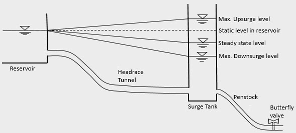
It is a chamber, provided in between low pressure tunnels and steeply sloping high pressure penstock pipes, that permits liquid to surge in it so as to minimize the effects of water hammer caused due to sudden acceptance and rejection of load in the turbine. During sudden closure of valve that feeds to the turbine, a wave of very high pressure is established in the pipeline system which may cause bursting of penstock pipe if proper safety measures are not provided. In order to counter this, either the thickness of penstock pipe should be increased or an open place should be provided to release the surge. The high pressure set up in the penstock pipe is released through the oscillation of water surface in surge chamber and is dampened by frictional resistance.
Functions of Surge Tank
- Protection of penstock pipe and low pressure tunnel from the effect of water hammer.
- Temporary storage of water when load on turbine is suddenly decreased (load rejection case)
- Temporary supply of water when load on turbine is suddenly increase (load acceptance case)
- It performs the function of head regulation.
Working Principle of Surge Tank
When load on turbine is suddenly decreased, water mass in penstock is rapidly decelerated and also the flow in tunnel is retarded. One part of continuous supply from tunnel then tend to fill the surge chamber and water level in surge chamber rises above static level in reservoir. Due to the counter pressure created by this over travel, flow in the tunnel is decelerated to the extent that the supply becomes smaller than the turbine demand. As a result, water level in the chamber starts to recede and will drop below steady state level. In an attempt to establish steady state condition, the water surface will again start to rises from low level and due to inertia of moving water, it will again over travel the steady state level. This cycle is repeated until the oscillation is dampened by friction.
When load on turbine is suddenly increased, the water level in surge chamber will fall abruptly below its initial position at reservoir level creating a sufficient head to accelerate the water mass in tunnel. This head difference becomes greater than that necessary to maintain steady flow at normal losses. Consequently, the discharge in tunnel increases and exceeds that required by turbine. As a result, surplus water will rise in the chamber above the initial static level. Now, similar to load rejection case, the water level in chamber will fall below steady state level due to counter pressure and will again over travel the steady state level while rising up. This cycle is repeated until the oscillation is dampened by friction.
