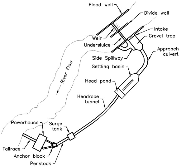
Fig: Schematic diagram of typical ROR type hydropower plant
Components of typical ROR type hydropower plant
The general layout and components of hydropower plants may differ based on the types of hydroelectric project. A general layout of typical ROR type hydropower plants constructed in Nepal is shown in figure above in schematic form. The name of each components is listed below:
1. Headworks Components
The diversion headwork is constructed in a hydro power plant so as to divert necessary amount of sediment free water into a waterway. A diversion headwork may consists of following components:
- Weir / Spillway
- Undersluice / Scouring sluice
- Divide wall
- Flood wall
- Side Intake
- Bed Sluice
- Gravel Trap
- Gravel Trap Side Spillway
- Approach Culvert / Approach Canal
- Settling Basin
- Head Pond
It is a long watercourse or passage that conveys water from headworks component to the a surge chamber or a forebay. The flow in the waterway may be either open channel or pipe flow. The structure in waterway my be one of the following types:
- Headrace Tunnel
- Headrace Canal
- Headrace Pipe
The chamber provided in between headrace pressure conduit and steeply sloping penstock pipes with a purpose to minimize the effect of water hammer is called surge tank. If the the waterway in headrace is of open channel type instead of pressurized system, forebay is installed in place of surge tank.
4. Penstock
It is a steel pipe that supplies water from surge chamber to the turbines placed inside powerhouse. Penstock pipe operates under very high water pressure.
5. Anchor Block and Saddle SupportThese are the structures that provide supports to the penstock pipe. Anchor blocks are provided at the bends where as saddle supports are provided in between the anchor blocks at regular spacing.
6. PowerhouseIt is a building which consists of different hydromechanical and electromechanical equipment in which hydraulic energy is converted into mechanical energy by turbines and the generators convert mechanical energy into electrical energy.
7. Tailrace Culvert / Tailrace CanalTailrace is a water channel constructed in the downstream of hydroelectric powerhouse in order to discharge water back to the river or other water bodies safely.
