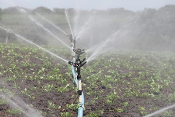

Sprinkler Irrigation
It is a method of irrigation in which water is spread uniformly over the land in the form of natural rainfall that comes from the nozzle of a sprinkler. Water is applied at the rate less than infiltration rate of soil so as to avoid any surface ponding and runoff. Also, the rate of application of water must match the rate of usage of water by the plants else the water will percolate deep below the root zones and will be lost to the plants. Surface ditches and prior land preparation is not necessary for sprinkler irritation system. It consists of a pipe network having main pipe, distribution pipe and laterals with the sprinklers placed at regular intervals along the lateral line. A sprinkler irrigation system can be of following different types:
- Permanent type
- Semi permanent type
- Portable type
If the distribution pipe and laterals are fixed in the land i.e. they are often buried then it is called permanent type sprinkler irrigation system. If the distribution pipes are fixed but laterals are movable from place to place then it is termed as semi permanent system. If the entire network can be moved from place to place then it is called portable type sprinkler irrigation system.
Advantages of Sprinkler Irrigation System
- Suitable to all types of soil except heavy clay.
- Suitable for both row and scattered cropping patters.
- Possibility of using soluble fertilizers and chemicals by mixing in water.
- Accurate and easy to measure amount of water distributed.
- No soil erosion as surface runoff can be completely eliminated.
Disadvantages of Sprinkler Irrigation System
- Sediment free water is necessary otherwise frequent clogging occurs.
- Efficiency of water distribution decreases under heavy winds.
- It is not suitable for paddy crops.
- Due to circular spraying of water, there is chance of over irrigation and no irrigation at some area.
Drip Irrigation
It is a method of applying water directly to the plants through a number of low flow rate outlets called emitters or drippers, generally placed at short interval along a small tubing. One of the main characteristics of this method is point irrigation as compared to area irrigation in sprinkler irrigation system. This method of irrigation is suitable only for row crops such as tomatoes.
Advantages of Drip Irrigation System
- Deep percolation and evaporation losses can be minimized because only small portion of ground (especially root zone of plants) is supplied with water.
- Weed growth can be controlled effectively.
- Surface runoff and soil erosion can be minimized.
- Fertilizers can be used with high efficiency.
- Field levelling is not necessary.
Disadvantages of Drip Irrigation System
- Sediment free water is necessary otherwise frequent clogging occurs.
- It is not suitable for scattered cropping patterns.
- Sun heat decreases the useful life of tubes used for drip irrigation.
- Waste of water, time, and harvest if not installed properly.
Suitability of Sprinkler and Drip Irrigation System for Hilly Areas
The sprinkler and drip irrigation methods are suitable for remote hilly area of Nepal because of following reasons:
- The necessary head for the operation of sprinkler and drip irrigation is easily available in hilly area due to its steep topography.
- Sediment free water is necessary for effective operation of sprinkler and drip irrigation system which can be obtained from spring sources in hilly areas.
- These methods can be adopted for both row and scattered cropping patterns. Drip irrigation method is applicable only for row crops where as sprinkler is suitable for both row and scatter crops.
- Drip and sprinkler irrigation system can be established with a simple pipe network in hilly areas where construction of headworks and canal structures is not feasible.
- Components of sprinkler and drip irrigation system can be transported easily to remote hilly areas.